The analog LED simulation electronic candle design comes from the use of real life candles. After the circuit is rebuilt, it can be used for candles in various occasions. The function of simulating LED simulation electronic candle can replace the function of compound candle, and it is a technology product that replaces traditional compound candle. Simply use electric, in-line or battery-type LED to simulate electronic candles. The colors of the lights are diverse, the styles and styles are diverse, and the market can greatly satisfy the needs of customers, safe use, and long-lasting. Let's take a look at the internal circuit principle of this candle:
LED simulation electronic candle
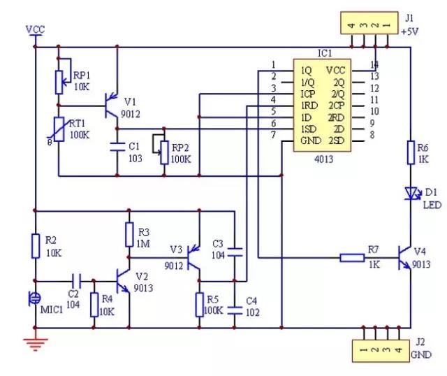
(1) The circuit utilizes a D flip-flop in the dual D flip-flop 4013 to form an R-S flip-flop. At the instant of turning on the power, the differential circuit composed of R4 and C3 generates a high-level differential pulse to be applied to the 1RD terminal of U1, forcing the circuit to reset, and the 1Q terminal outputs a low level to the base of the transistor VT4, so that VT4 is turned off. The light emitting diode LED1 does not emit light.
(2) When the thermistor RT1 is burned with a lighter (the burning time should not be too long, otherwise the thermistor is easily burned out), the resistance of RT1 suddenly becomes small, showing a low resistance state, making the base of the triode VT1 extremely low. Flat, triode VT1 (9012) is turned on, the high-level pulse generated at the collector of VT1 is sent to the 1SD terminal of 4013, so that the 1Q terminal is turned to a high level, and is sent to the base of the transistor VT4, which is also a high level. , VT4 conduction, LED simulation electronic candle LED LED1 light. This process is equivalent to lighting the candle with a match. At this time, even if the lighter leaves the thermistor RT1 (the temperature returns to normal), the state of the circuit does not change, and the LED 1 remains illuminated.
(3) When using the mouth to blow the LED to simulate the electronic candle electret microphone M1, the electret microphone M1 has a short internal conduction, but the voltage of the capacitor C2 cannot be abrupt, so that the base of the VT2 exhibits a short negative voltage (using the number The multimeter measures about -1V). As the electret microphone M1 returns to normal, the base voltage of VT2 rises from a negative voltage to 0V, presenting a low to high change signal, resulting in a high to low change signal at the collector of VT2. The base potential of the PNP transistor VT3 drops, causing VT3 to conduct, and a high-level pulse is generated at the collector of VT3 to the "RS flip-flop" 1RD terminal. The "RS flip-flop" is reset, the 1Q terminal changes from high level to low level, VT4 is turned off, and the LED 1 is turned off, realizing the simulation effect of "wind blowout".


 中文网站
中文网站